Determine Secondary Oven Offset and Secondary Column Length
Purpose: To maximize peak distribution within the two dimensional space by adjusting the secondary oven temperature offset and/or length of column in the secondary oven.
Experiments:
With the recommended columns, inlet and temperature programs make two methods with the following modifications:
1) Set the Modulation Period and Hot Pulse Times in both methods to 10 and 3 seconds respectively.
2) Set the Secondary Oven Offset in one method to +5 °C and the other to +40 °C.
Make an injection of a representative sample or standard with each method. You will note the Method Modulation Period is 10 sec for this evaluation. The long modulation period will decrease the resolution in the first dimension, but this isn’t important in this step. It is set purposely long to prevent any peaks from wrapping around the second dimension. Once this evaluation is complete the Method Modulation Period will match the Optimal Modulation Period.
Step 12 of 19
Determine Secondary Oven Offset and Secondary Column Length
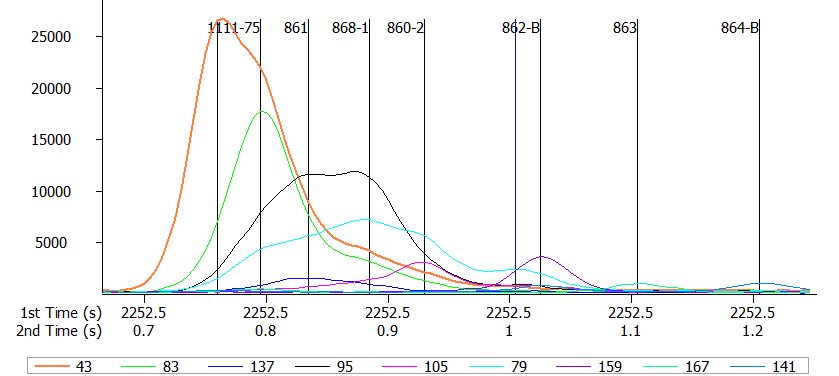
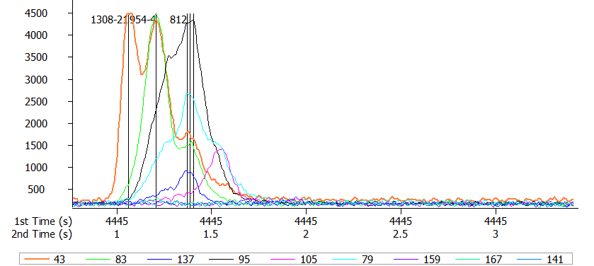
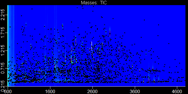
Process the data. Check that there is no wraparound and identify the last eluting peak in the second dimension. See the example contour plot below. Input the retention time of last eluting peak in the second dimension from each run into Simply GCxGC.
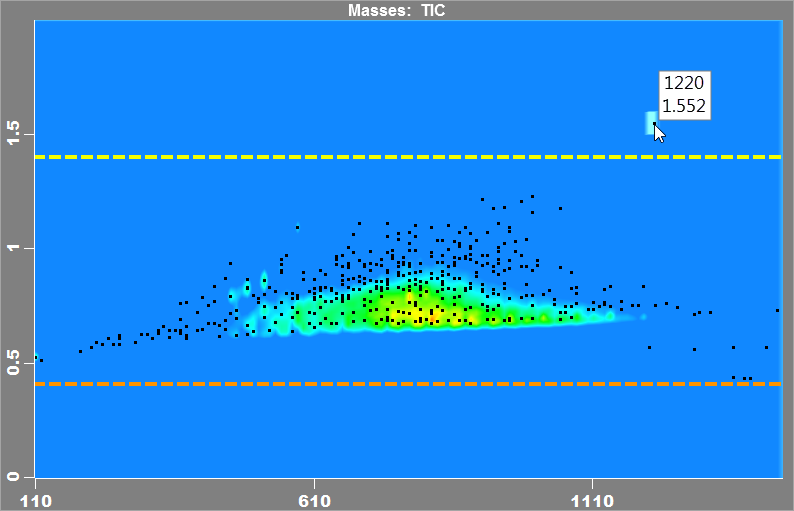 Run with +5 °C offset. The onscreen tooltip shows the first and second dimension retention times (1220, 1.552). The yellow line is the Optimal Modulation Period + Secondary Column Void Time. The orange line is the Secondary Column Void Time. This example is one of several possible results.
| Result Scenario | How will Simply GCxGC Respond? | What is Your Next Step? |
| The last +5 °C injection peak elutes after the Optimal Modulation Period + Secondary Column Void time AND the last +40 °C injection peak elutes between the Optimal Modulation Period + Secondary Column Void time and the Secondary Column Void time. |
Simply GCxGC will calculate an optimal Secondary Oven Offset and reset the Method Modulation Period and Hot Pulse Times to the optimal conditions. | Create a new method with the updated settings shown in the Summary view, and re-inject the same sample or standard to confirm offset. The last eluting peak will elute just before the Secondary Column Void time of the next modulation. |
| In both injections, the last peak elutes after the Optimal Modulation Period + Secondary Column Void time. | The peaks are being retained too long in the secondary oven. | Either remove a loop of column from the secondary oven and retest, or evaluate new stationary phase(s). |
| In both injections, the last peak elutes before the Optimal Modulation Period + Seconary Column Void time. | The peaks are not being retained long enough in the secondary oven. | Either add a loop of column to the secondary oven and retest or evaluate new stationary phase(s). |

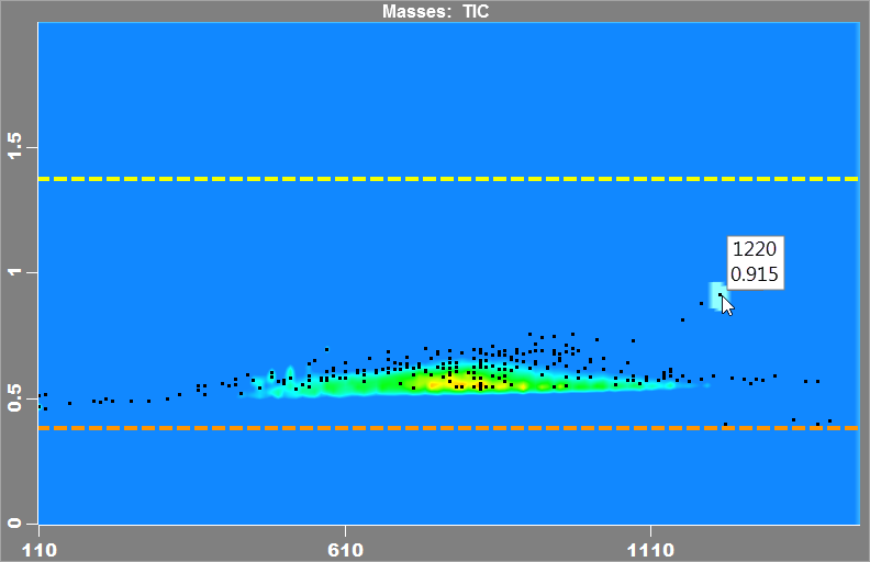
Injection with Secondary Oven Offset set to +40 °C. The latest eluting peak appears between the Optimal Modulation Period + Secondary Column Void time and the Secondary Column Void time.
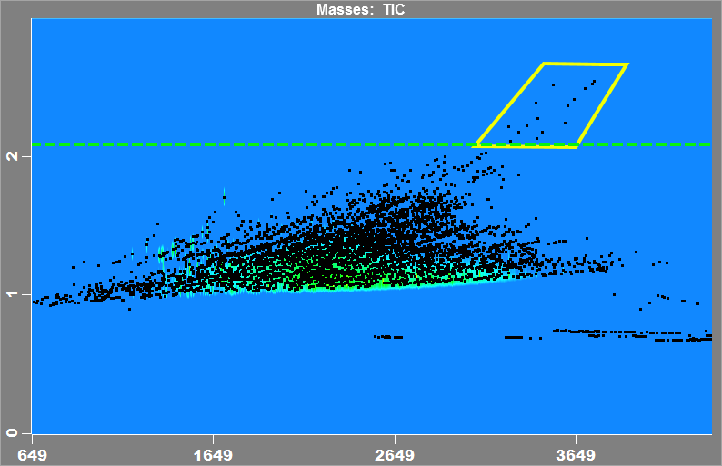
When the sample is recollected with the optimal modulation period, the peaks in the yellow box wrap around to the next modulation period and appear in the secondary column’s void space.
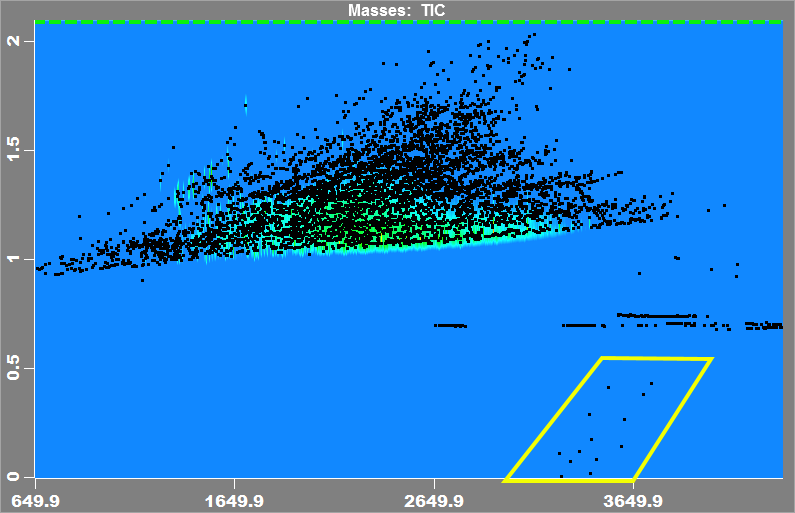
By utilizing the void space, you are able to maximize the separation between the peaks in your sample. If a peak straddles the boundary, ChromaTOF is still able to integrate the slices correctly and aggregate all slice areas into a single entry in the Peak Table.
Step 13 of 19
Determine Secondary Oven Offset
Step 14 of 19
Calculated Secondary Oven Offset
Step 15 of 19
Calculated Secondary Oven Offset
Remove a loop from the secondary oven.
Update Method with new secondary column length.
Rerun experiment.
Step 15 of 19
Calculated Secondary Oven Offset
Add a loop to the secondary oven.
Update Method with new secondary column length.
Rerun experiment.
Step 15 of 19
Calculated Secondary Oven Offset
Step 15 of 19
Convert 1D to GCxGC
Purpose: Select basic system configurations options and begin the process of creating a GCxGC method from scratch or transmuting an existing 1D method to GCxGC.
In this section, the instrument is selected to set parameters specific to that instrument, including transfer line length, outlet pressure, and maximum data acquisition rate. Other user-selected parameters in this section include carrier gas type, primary column dimensions, transfer line temperature, and whether an uncoated column will be installed in the transfer line.
For the primary column, dimensions of an established one-dimensional method can be used as a starting point, or you may select one of two suggested columns.
You may choose to use an uncoated column in the transfer line rather than extending the length of the secondary column. An uncoated transfer line column is given as a choice for those cases when the secondary column must be ramped to its maximum operating temperature. If the second dimension column is installed in the transfer line, significant retention will occur for the analytes eluting at the column’s maximum temperature. This is generally not an issue for 1-dimensional separations, but it is a problem for the fast separation in the second dimension. To eliminate this retention, it is recommended that an uncoated column be installed, especially for the longer transfer line of the Pegasus® GC-HRT 4D. Additionally, the transfer line acts as a restrictor. The longer the transfer line and the narrower its diameter, the greater the restriction. To minimize this, LECO recommends you use an uncoated column with an ID of the next larger standard size. For a 0.25 mm ID, a 0.32 mm ID would be recommended; however, a 0.32 mm ID column will not coil in the secondary oven without breaking. So a for a 0.25 secondary column, install a 0.25 mm ID transfer line column. For secondary columns with smaller IDs, the rule of using a transfer line column with the next largest size applies.
Step 2 of 19
Select Instrument
Step 3 of 19
Step 4 of 19
Note: If you have a previously developed one-dimensional GC method, this column may be a good starting point for the primary column.
If you do not have a previously developed 1 dimensional method,the following dimensions are recommended: 30 m x 0.25 mm x 0.25 µm for most cases, or 60 m x 0.25 mm x 0.25 µm for more complex samples.
Guard columns installed between the GC inlet and primary column do not have any effect on peak separation and are not tracked by Simply GCxGC.
Step 5 of 19
Step 6 of 19
1. You are using a system with a long transfer line e.g. Pegasus-HRT.
2. You anticipate your temperature program will include an isothermal hold at the end of your run at or near the maximum temperature of your secondary column.
Step 7 of 19
Step 8 of 19
Decrease Run Time
Step 18 of 19
Decrease Run Time
The run time cannot be decreased safely for the current column configuration.
Congratulations
You have successfully made a robust GCxGC methodStep 19 of 19
Evaluate Peak Capacity (Resolution)
Purpose: Examine peak separation more closely. You will determine if the peak capacity (chromatographic resolution) of the separation is sufficient (Good), excessive (also Good but may allow you to decrease run time later), or insufficient (Need More or Need more in Second Only). Need More increases overall peak capacity, while Need More in Second Only increases peak capacity in the secnd dimension specifically.
Select "Good" if the separation meets your assay’s requirements. The next step is an optional consideration to Decrease Run Time.
Select "Need More" if the separation is not acceptable and more peak capacity is needed in both dimensions. The next step is Increase Peak Capacity.
Select "Need More in Second Only" if the resolution in the first dimension is acceptable, but more resolution (peak capacity) is needed in the second dimension. If the selected stationary phase combination is partially successful at separating your peaks increasing the peak capacity can possibly help at the cost of slowing down the analysis. If after increasing the peak capacity the separation is still marginal choosing a different stationary phase combination may be required.
In the comparison below, we have the benefit of seeing the difference between two examples of the same sample. However, you will typically be evaluating a single data file. Look for well separated peaks to determine how a single peak should appear. Now look for peaks in the first dimension that appear distorted from coelution and/or are wider than expected. Note the first peak (peak on the left) in Figure 1; it is either a poor peak shape or two peaks merging together. The second peak appears to be a single peak, but wide compared to an isolated single peak. In Figure 2 you can see that the first peak that looked like two might actually be four. The second peak in Figure 1 is clearly two peaks in Figure 2. The color settings in the contour plot can significantly affect the appearance of a peak. If there is some uncertainty about the peak(s)’ appearance in the contour plot, adjust the color settings. After examining peaks throughout the first dimension, decide if the resolution is acceptable.
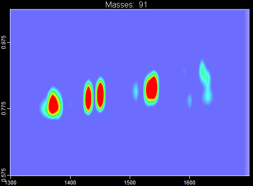
Figure 1: Poor First Dimension Separation
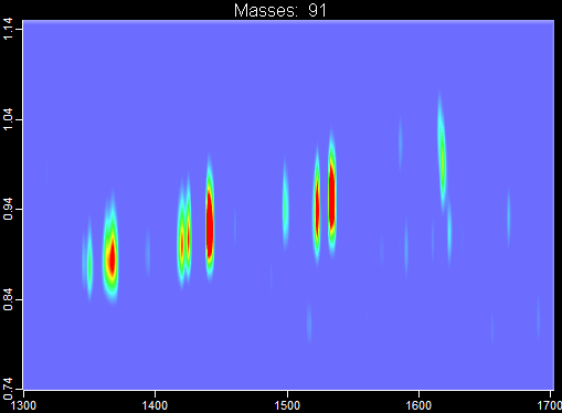
Figure 2: Improved First Dimension Separation
Look for peaks in the second dimension that are in the same modulation and are closely eluting. Zoom in and examine the prominent or unique masses in both the contour plot and chromatogram. Note the resolution between peaks for selected m/z’s. Review both contour plot data and chromatogram data. Look for well separated peaks to determine how a well resolved peak should appear, and evaluate the chromatographic resolution and deconvolution results for closely eluting peaks. See the examples below.
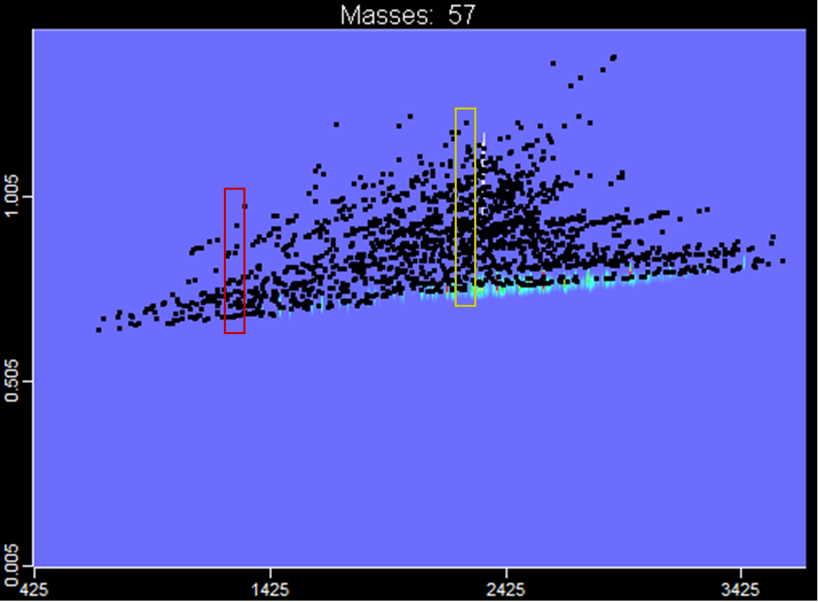 This was the best possible separation from the Determine Secondary Oven Offset and Secondary Column Length example with the given stationary phase combination. It did not meet the Evaluate the Stationary Phase criteria, but you may have decided to continue on anyway to see what might be possible.
In the less-peak-dense regions (red rectangle) the separation may be sufficient. Zoom in on the chromatogram and display the unique masses of the different analytes. This separation is probably acceptable with deconvolution. However, a better stationary phase combination should be considered.

In a dense-peak area (yellow rectangle), the separation is much more congested.
 It appears that deconvolution may be more difficult compared to the earlier part of the separation. More peak capacity may help, but a different stationary phase combination is also a consideration. With the peaks closely eluting early in the second dimension separation, a reversal of the stationary phases is also a possible solution.
In the figure below, the sample was run again with the temperature program slowed to improve peak capacity.
 There is some improved resolution, but still poor separation. Again, a change in stationary phase combination is indicated. As in single dimension, further changes to increase peak capacity can be tested, but a more selective stationary phase combination is more likely to lead to an acceptable separation.
Step 17 of 19
Exchange Peak Capacity
Glossary
- Acquisition Rate
- The calculated, minimal Acquisition Rate for your MS method. This value is based on the expected average second dimension peak width and is limited by the maximum Acquisition Rate for the selected instrument. The data rate recommended provides ~ 10 spectra per FWHH for best deconvolution. Note: This value only applies to LECO TOF MS systems.
- Carrier Gas
- The carrier gas selected by the user. If no gas is selected, He (Helium) is selected by default.
- Critical Loadability (Primary and Secondary columns)
- The critical volume of the stationary phase in each column that is proportional to the maximum amount for sample loading. These numbers are compared to each other to understand the columns’ relative loading capacities. For example, if the primary column has a value of 20nL and the secondary column a value of 2nL, the secondary column has one tenth the loadability (maximum amount that can be loaded). In general, the loadability of the GC×GC system is limited by the secondary column.
- Detailed
- When selected, this option will expand the Summary section to show additional values.
- Flow
- By default, the calculated optimal flow rate, based on the column’s dimensions and carrier gas. This value may be overwritten by the user.
- History Table
- Sorted by most recent to oldest, this table is updated as new values are calculated. Selecting a row will load the associated settings.
- Inlet Pressure at Temperature
- A calculated value based on the selected column configuration, flow rate, carrier gas type, and maximum temperature. The field text will turn red if the pressure exceeds 150 psi (~1030 kPa). Note: Some standard GC inlets are limited to 100 psi (~690 kPa).
- Method Modulation Period
- Typically the same as the Optimal Modulation Period, unless the user enters a new modulation period, or, during the Determine Secondary Oven Offset step, the tool will intentionally set an exaggerated Method Modulation Period to avoid potential wraparound peaks from distorting the calculations.
- Method Hot Pulse Time
- Portion of the modulation period allotted to each of the two hot jets. A typical starting point is to set the Hot Pulse Time equal to 30% of the modulation period. All Pegasus-HRT and most Pegasus-GC systems will allow you to change the Hot Pulse Time during the run to accommodate the later-eluting, harder-to-desorb compounds.
- Optimal Modulation Period
- A calculation of the optimal modulation period, based on the expected first dimension peak widths.
- Oven Temperature Program
- Basic temperature program without holds, a single ramp condition and assumes a temperature range of 40-300 C unless the temperature range is changed by the user.
- PC 1
- See Peak Capacity, Primary Column.
- PC 2
- See Peak Capacity, Secondary Column.
- PC Net
- See Peak Capacity, Net.
- Peak Capacity Gain
- The peak capacity factor increase realized when running a GCxGC method compared to an equivalent single dimension (1D) analysis with the same column and conditions.
- Peak Capacity, Net
- The calculated peak capacity for the combination of both columns and for modeling for peak stacking in the secondary dimension.
- Peak Capacity, Primary Column
- Peak capacity of the primary column per run. This calculation includes a small first dimension peak capacity loss due to the modulation process. Other calculators may not account for this loss.
- Peak Capacity, Secondary Column
- Peak capacity of the secondary column per modulation period.
- Primary Column
- The dimensions and phase of the first dimension column located in the primary oven. This does not include any length of guard column the user may add between the inlet and analytical column. The guard column is not needed in the calculations of the tool and has no effect on the results relative to the calculations.
- Primary column velocity
- The average velocity of the carrier gas through the primary column.
- Run Time
- The calculated run time based on the Oven Temperature Program plus Initial Hold Time. The Run Time does not include holds at the end of the run and assumes a single temperature ramp. Additional holds or changes to the temperature range in the method loaded into your GC will obviously change your method’s run time. Changes to the ramp rate will likewise change your run time but may also affect your method’s actual peak capacity and separation characteristics.
- Secondary Column
- The dimensions and phase of the second dimension column located in the secondary oven. The internal circumference of a LECO second dimension oven is approximately 0.15 m. Note: When using the same ID for both the primary and secondary columns, the additional length of the secondary column in the GC oven has negligible effect on the actual results relative to the calculation of the tool which ignores this length. When using a larger bore secondary column, the additional length in the GC oven similarly has a negligible effect. However, when the secondary column is a narrower bore relative to the primary column, the additional length of the secondary column in the GC oven has a significant effect and is not accounted for in the calculations of the tool. Therefore, this additional length should be minimized (< 20 cm) for best agreement between the calculated and actual peak capacity results.
- Secondary Oven Temperature Offset
- The positive value difference in temperature between the primary and secondary ovens. It is assumed that the secondary oven’s temperature program will ramp with the Oven Temperature Program.
- Transfer Line
- The dimensions and phase of the column in the transfer line. The column may either be a continuation of the secondary column or an uncoated column connected in the secondary oven to the outlet of the secondary column.
- Transfer Line Temperature
- A static temperature set by the user. This value should be less than the maximum temperature for the transfer line column’s phase.
- Void Time, Primary Column
- The time it takes an unretained peak to move though the primary column.
- Void Time, Secondary Column
- The amount of time required for an unretained peak to pass through the secondary oven and transfer line columns. Any peak that elutes before this time in the second dimension has “wrapped-around” from a previous modulation cycle.
Introduction to Guide Me
The purpose of the Guide Me mode is to provide logical, step-by-step instructions that guide you through the process of developing an optimized GCxGC method.
The Guide Me mode has two components:
1) A computational engine which calculates column dimensions and operating parameters for optimum peak capacity.
2) A logical experimental scheme for evaluating and modifying the separation.
A GCxGC separation depends on column dimensions and operating parameters (peak capacity) which can be calculated; however, the actual distribution of peaks in the two-dimensional separation plane depends largely on the stationary phase chemistry and the particular sample components. Therefore, the development scheme guides you through the experimentation necessary to adjust the retention in the second dimension, optimize the stationary phases, and modify (increase, decrease, redistribute) the peak capacity as required by the goals of your application.
Step 1 of 19
Increase Peak Capacity
Increase Peak Capacity
The peak capacity cannot safely be increased for the current column configuration.
Increase Secondary Column Peak Capacity
Note: It is recommended to keep the excess length of the secondary column that resides in the GC oven to a minimum. This narrower bore piece acts as a restrictor and it is best to limit its effect on the first dimension.Increase Secondary Column Peak Capacity
The secondary column peak capacity cannot safely be increased for the current configuration.
Evaluate Sample Loading
Purpose: Determine proper sample loading on the column by the experiment.
Experiments:
• Install the column set and create necessary methods with recommended conditions.
• Inject the representative sample or standard.
• Evaluate the most intense peaks for overloading. If overloaded, reduce the amount injected on column and revaluate.
• Evaluate known, low concentration peaks (if any) for sufficient loading. If more sample loading is needed for low level analytes and the most intense peaks are not interfering or overloaded, then increase amount injected on column.
You’ll start by selecting some of your most abundant analytes of interest, looking for signs of phase overloading. You should also look at other, closely eluting peaks for comparison and potential interferences. If you have a list of lower concentration target peaks, you should look for those as well and ensure they are detected.
Sort the Peak Table by Area so the largest peaks are grouped together, keeping in mind that saturated peaks may have their area divided among multiple peak markers. Starting with the most abundant entries double-click on each analytically important peak. Overloaded peaks will present in the Chromatogram with fronting or tailing and be significantly wider, compared to less abundant neighboring peaks or less abundant slices of the same analyte. Some peaks may be poorly shaped for reasons unrelated to phase overloading, so your evaluation should be based on several different peaks over the course of the run.
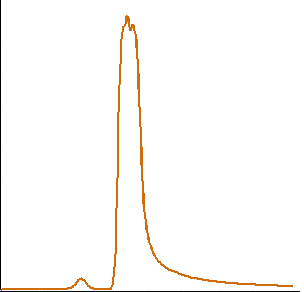
Overloaded Peak
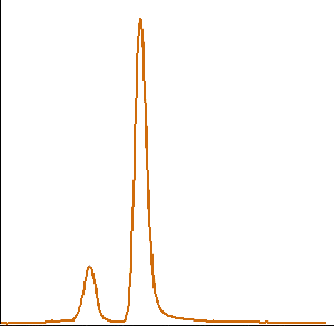
Acceptable Peak
Note that time axis is scaled the same for both.
If your sample appears to be overloading the phase and your lower concentration target analytes are easily detected consider injecting less sample onto the column. Note that using a thicker film will also increase retention changing the secondary oven offset and secondary column length required. If overloading does not appear to be an issue you can choose to continue on as is or try injecting more sample onto the column to boost detection of lower concentration peaks.
Other Considerations
A column set with 0.25 mm ID is recommended for best sample loading. The secondary column limits the sample loading; therefore, if a smaller bore secondary column is used, the loading on the primary column must be decreased.
To increase the column loading capacity you can also try a thicker film column. Keep in mind this will also increase retention so changing the secondary oven offset and secondary column length (if established) is required.
Initially, a long modulation period (10 sec) is used in this step to avoid having peaks wrap around. If the peaks are marginally overloaded, using the optimum modulation period will reduce the loading somewhat, so slight overloading in one modulation may be acceptable once you transition to the optimal modulation period.
Step 10 of 19
Sample Loading Evaluation
This is the start of the experimental part of the method development tool.Using the parameters shown in the summary build a GC method and collect a representative sample. Then use the Contour plot look at the TIC, if you have peaks that are overloaded that are in an area of interest you will need to either inject less sample (first choice) or switch to wider column bore (in general 0.25 mm should be the widest bore used).
Step 11 of 19
Evaluate Stationary Phase
Purpose:Evaluate the final separation of the previous step and determine if the selected stationary phase chemistries, in combination with optimized method settings, adequately distribute the peaks throughout the two-dimensional space and provide the required chromatographic resolution for the application.
Experiments: Optional injections as described in the Evaluation section.
If the peak distribution is not acceptable, select Bad to return to the Stationary Phase Combinations step. If the stationary phases are acceptable, select Good to move on.
Evaluate the contour plot for the goodness of separation in the first and second dimensions relative to the stationary phases and selectivity; see Examples below. Note that a poor selection of stationary phases cannot be corrected by column dimensions and conditions.
If the peak distribution is not acceptable select Bad to return to the Stationary Phase Combinations step. If the stationary phases are acceptable, select Good to move on.
Differentiate selectivity from peak capacity. If separations are close to adequate, consider increasing peak capacity (later step). However, if the first dimension peak capacity is already high and critical peaks show very little separation or perfectly coelute, then consider changing the stationary phase(s) to improve selectivity.
If most of the peaks are clustered in a relatively tight horizontal band and are not filling the optimum modulation period, a change in stationary phases is needed. If the first dimension separation appears reasonable, consider just changing the secondary column phase.
Step 16 of 19
Select Stationary Phase
Purpose: Select stationary phases for the primary and secondary columns, based on guidelines and/or other knowledge with respect to the sample and stationary phases.
Basic Guidelines:
If you are converting an established 1D method, use the same stationary phase for the primary column and select a complementary stationary phase for the secondary column. The provided table (Phase Suggestions) lists some typical, proven stationary phase combinations. As a starting point, the primary and secondary columns will have the same ID and film thickness.
For new users, selecting appropriate phase combinations for their samples can be an intimidating step. You may use phase combinations from your personal experience, the provided table, or from journal articles. Additionally, most column vendors have a GC column selection guide you can review, and you may contact LECO’s Applications Group at [email protected] for assistance. In addition to the phase chemistries, there are some additional considerations:
• The primary column has much more resolving power than the secondary column. Select the primary stationary phase for the most difficult separations, typically those analytes of same or similar functionality.
• The secondary column is best suited for separating different functionalities. Select the secondary stationary phase based on different analyte functionalities within the sample.
• Keep in mind the maximum temperature of both phases. A high temperature phase can be limited by pairing it with a low temperature counterpart.
• Consider both non-polar/polar combinations and polar/non-polar combinations.
• The most common and default stationary phase combination is Primary Column, Rxi-5MS or Rxi-5SilMS (5% phenyl); Secondary Column, Rxi-17SilMS (50% phenyl).
| Application Area |
Primary Column | Secondary Column | ||
| Phase | Selectivity | Phase | Selectivity | |
| Petrochemical | Rxi®-1ms | Non-polar | Rxi®-17Sil MS | Mid-polar, aromatic selective |
| Petrochemical | Rxi®-5Sil MS | Non-polar | Rxi®-17Sil MS | Mid-polar, aromatic selective |
| PAHs, environmental | Rxi®-17Sil MS | Mid-polar, aromatic selective | Rxi®-1ms | Non-polar |
| PAHs, environmental | Rxi®-17Sil MS | Mid-polar, aromatic selective | Rxi®-5Sil MS | Non-polar |
| PCBs, PBDEs, PAHs, environmental | Rxi®-XLB | Non-polar | Rxi®-17Sil MS | Mid-polar, aromatic selective |
| Mono-ortho, coplanar PCBs | Rxi®-1ms | Non-polar | Rxi®-XLB | Planar selective |
| Mono-ortho, coplanar PCBs | Rxi®-5Sil MS | Non-polar | Rxi®-XLB | Planar selective |
| Pesticides, nitroaromatics, halogenated compounds | Rxi®-1ms | Non-polar | Rtx®-200 | Mid-polar, electronegative selectivity |
| Pesticides, nitroaromatics, halogenated compounds | Rxi®-5Sil MS | Non-polar | Rtx®-200 | Mid-polar, electronegative selectivity |
| Pesticides, nitroaromatics, halogenated compounds | Rxi®-XLB | Non-polar | Rtx®-200 | Mid-polar, electronegative selectivity |
| Flavors, fragrances | Rxi®-1ms | Non-polar | Stabilwax® | Polar |
| Flavors, fragrances | Rxi®-5Sil MS | Non-polar | Stabilwax® | Polar |
| Flavors, fragrances | Stabilwax® | Polar | Rxi®-1ms | Non-polar |
| Flavors, fragrances | Stabilwax® | Polar | Rxi®-5Sil MS | Non-polar |
Step 9 of 19
Simply GCxGC®
The purpose of the Advanced tool is to allow the user to change column dimensions and operating parameters to explore the effect of such changes on peak capacity.
The Advanced tool uses the underlying computational engine that is used in the Guide Me tool. The user can change individual parameters while holding the other parameters fixed to calculate peak capacity. With this tool the user can learn what effects the various parameters have on the peak capacity and can explore ways to fine tune a separation. These changes can be compared to those optimum results calculated in the Guide Me tool.
Columns
Increase Peak Capacity
Increase Peak Capacity
Select Instrument
Units and Settings
Simply GCxGC® for Thermal Modulation
Introduction:
Simply GCxGC is designed to help you create a generally optimized GCxGC method for a thermal modulation system. Simply GCxGC will offer suggestions for optimized conditions, or you may enter your own values if you have a previously established GC method. Later steps will guide you through determining the secondary oven offset, second dimension column length, and experimentally evaluating the stationary phases and peak capacity. Working through these steps should help you avoid unnecessary testing and streamline your method development cycle.
Simply GCxGC assumes that you understand the basics of gas chromatography and GCxGC. Simply GCxGC will explain some concepts as you move along, but if you are new to gas chromatography or GCxGC theory, LECO recommends the following source for more information. Comprehensive Chromatography in Combination with Mass Spectrometry, Luigi Mondello, Ed., John Wiley & Sons, Inc
• Optimize the two main parts of the separation, selectivity and peak capacity. Selectivity is controlled by the combination of two stationary phases. It is important to keep in mind that issues stemming from an unsuitable stationary phase combination cannot be corrected through method development. However, reasonable stationary phase combinations may be helped by optimizing column dimensions and operating conditions. Peak capacity is dictated by the dimensions of the column set and operating conditions (flow, heating rate, modulation period).
• Improve the speed of a separation. In general GCxGC is utilized for complex samples. However, GCxGC does have the potential to separate faster than a traditional 1-dimensional separation. For example, an acceptable 1-dimensional separation may be achieved on a 60 m column; however, it may be possible to achieve the same desired separation in GCxGC with a 30 m primary column in less time. Of course, this is sample dependent.
• How to do injections (split, splitless) and how to change the amount injected on column.
• How to operate a GC-MS system.
• The basics of stationary phase selection.
• The chromatographic effects of GC operating parameters like flow and heating rate.
• How to create a basic data processing method and preform basic peak selection actions within ChromaTOF..
Simply GCxGC was designed around LECO’s thermal modulation systems. In some cases, you can extrapolate to other thermal modulation systems: however, results may be poorer than predicted due to a wider reinjection as compared to the LECO systems. Extrapolation to flow modulation systems is generally not possible.
Simply GCxGC cannot automatically determine the best separation but will help you evaluate the overall separation of your method. You may need to further refine your method to deal with critical areas in your samples. At this point your chromatography skills will be key.
Simply GCxGC can help you with general column phase selection. Simply GCxGC lists some of the more common phases for the general application categories, but it cannot calculate the optimum stationary phase chemistries for your specific application. For more information on selecting a column set for your application, LECO suggests you contact your column vendor’s technical support or LECO’s Applications Group at [email protected].
Initially, Simply GCxGC guides you to evaluate sample loading. If there is overloading, you are directed to decrease the amount injected on column. Additionally, if there are known, low concentration analytes, you use this step to make sure they are detected.
Next, Simply GCxGC guides you through the necessary experiments to determine the secondary oven offset and, if necessary, adjustment of the length of secondary column in the secondary oven. For these injections, Simply GCxGC will give you temporary settings to ensure the peaks do not wrap around in the second dimension.
Simply GCxGC then steps you through evaluating the stationary phases based on the separation in each dimension. If you are happy with your method, you may use it as is, make small changes specific to your samples (hot pulse time, isothermal hold at the end of the run, etc.), or move onto to optional steps to improve peak capacity or decrease run time.
After experimentally adjusting the sample loading, second dimension column length, secondary oven offset, and stationary phases, Simply GCxGC guides you in evaluating the separation (resolution/peak capacity) in each dimension. Simply GCxGC then shows you how to make the necessary changes to adjust the separation based on the column dimensions and operating conditions. Options for increasing peak capacity or decreasing run time are calculated and shown to you during this step.
| # | Run Time | PC 1 | PC 2 | PC Net |
|---|